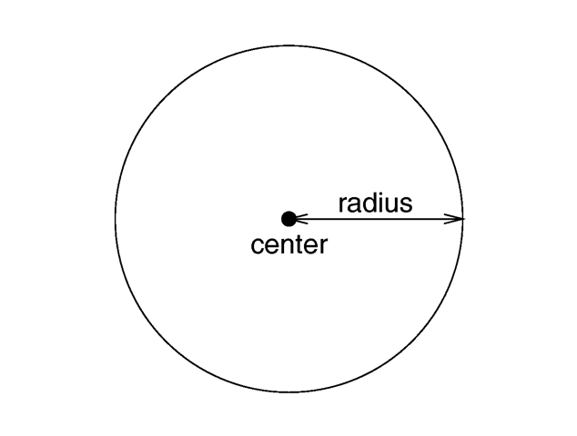
The geometry of a sphere.

Where <CENTER> is a vector specifying the x, y, z coordinates of the center of the sphere and RADIUS is a float value specifying the radius. Spheres may be scaled unevenly giving an ellipsoid shape.
Because spheres are highly optimized they make good bounding shapes (if manual bounding seems to be necessary).
The values of e and n, called the east-west and north-south exponent, determine the shape of the superquadric ellipsoid. Both have to be greater than zero. The sphere is e. g. given by e = 1 and n = 1.
The syntax of the superquadric ellipsoid, which is located at the origin, is:
Two useful objects are the rounded box and the rounded cylinder. These are declared in the following way.
The roundedness r determines the roundedness of the edges and has to be greater than zero and smaller than one. The smaller you choose the values of r the smaller and sharper the edges will get.
Very small values of e and n might cause problems with the root solver (the Sturmian root solver cannot be used).
The points <POINT0> through <POINTn-1> are two-dimensional vectors consisting of the radius and the corresponding height, i. e. the position on the rotation axis. These points are smoothly connected (the curve is passing through the specified points) and rotated about the y-axis to form the SOR object. The first and last points are only used to determine the slopes of the function at the start and end point. The function used for the SOR object is similar to the splines used for the lathe object. The difference is that the SOR object is less flexible because it underlies the restrictions of any mathematical function, i. e. to any given point y on the rotation axis belongs at most one function value, i. e. one radius value. You can't rotate closed curves with the SOR object.
The optional keyword open allows you to remove the caps on the SOR object. If you do this you shouldn't use it with CSG anymore because the results may be wrong.
The SOR object is useful for creating bottles, vases, and things like that. A simple vase could look like this:
One might ask why there is any need for a SOR object if there is already a lathe object which is much more flexible. The reason is quite simple. The intersection test with a SOR object involves solving a cubic polynomial while the test with a lathe object requires to solve of a 6th order polynomial (you need a cubic spline for the same smoothness). Since most SOR and lathe objects will have several segments this will make a great difference in speed. The roots of the 3rd order polynomial will also be more accurate and easier to find.
The slower but more accurate Sturmian root solver may be used with the surface of revolution object if the shape does not render properly.
The following explanations are for the mathematically interested reader who wants to know how the surface of revolution is calculated. Though it is not necessary to read on it might help in understanding the SOR object.
The function that is rotated about the y-axis to get the final SOR object is given by
with radius r and height h. Since this is a cubic function in h it has enough flexibility to allow smooth curves.
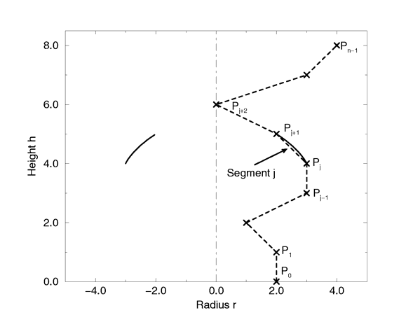
The curve itself is defined by a set of n points P(i), i=0...n-1, which are interpolated using one function for every segment of the curve. A segment j, j=1...n-3, goes from point P(j) to point P(j+1) and uses points P(j-1) and P(j+2) to determine the slopes at the endpoints. If there are n points we will have n-3 segments. This means that we need at least four points to get a proper curve.
The coefficients A(j), B(j), C(j) and D(j) are calculated for every segment using the equation
where r(j) is the radius and h(j) is the height of point P(j).
The figure below shows the configuration of the points P(i), the location of segment j, and the curve that is defined by this segment.
Where fontname.ttf is the name of the TrueType font file. It is a quoted string literal or string expression. The string expression which follows is the actual text of the string object. It too may be a quoted string literal or string expression. See section "Strings" for more on string expressions.
The text will start with the origin at the lower left, front of the first character and will extend in the +x-direction. The baseline of the text follows the x-axis and decenders drop into the -y-direction. The front of the character sits in the x-y-plane and the text is extruded in the +z-direction. The front-to-back thickness is specified by the required value THICKNESS_FLOAT.
Characters are generally sized so that 1 unit of vertical spacing is correct. The characters are about 0.5 to 0.75 units tall.
The horizontal spacing is handled by POV-Ray internally including any kerning information stored in the font. The required vector OFFSET_VECTOR defines any extra translation between each character. Normally you should specify a zero for this value. Specifing 0.1*x would put additional 0.1 units of space between each character.
Only printable characters are allowed in text objects. Characters such as return, line feed, tabs, backspace etc. are not supported.
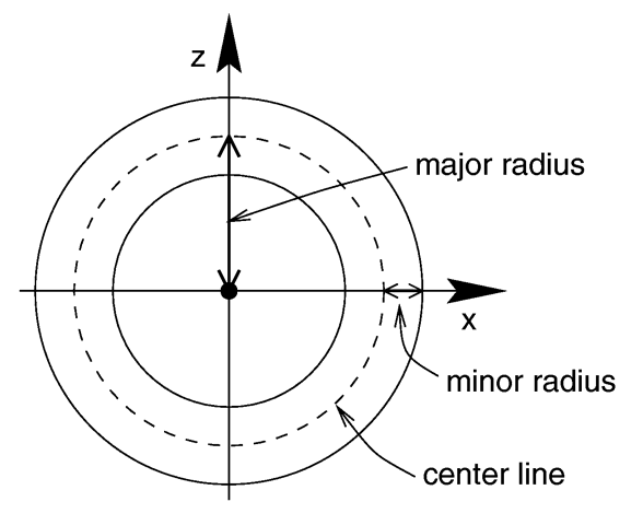
where MAJOR is a float value giving the major radius and MINOR is a float specifying the minor radius. The major radius extends from the center of the hole to the mid-line of the rim while the minor radius is the radius of the cross-section of the rim. The torus is centered at the origin and lies in the x-z-plane with the y-axis sticking through the hole.
The torus is internally bounded by two cylinders and two rings forming a thick cylinder. With this bounding cylinder the performance of the torus intersection test is vastly increased. The test for a valid torus intersection, i. e. solving a 4th order polynomial, is only performed if the bounding cylinder is hit. Thus a lot of slow root solving calculations are avoided.
Calculations for all higher order polynomials must be very accurate. If the torus renders improperly you may add the keyword sturm after the MINOR value to use POV-Ray's slower-yet-more-accurate Sturmian root solver.
The keyword type is followed by a float PATCH_TYPE which currently must be either 0 or 1. For type 0 only the control points are retained within POV-Ray. This means that a minimal amount of memory is needed but POV-Ray will need to perform many extra calculations when trying to render the patch. Type 1 preprocesses the patch into many subpatches. This results in a significant speedup in rendering at the cost of memory.
The four parameters type, flatness, u_steps and v_steps may appear in any order. They are followed by 16 vectors that define the x, y, z coordinates of the 16 control points which define the patch. The patch touches the four corner points <CP1>, <CP4>, < CP13> and <CP16> while the other 12 points pull and stretch the patch into shape. The Bezier surface is enclosed by the convex hull formed by the 16 control points, this is known as the convex hull property.
The keywords u_steps and v_steps are each followed by float values which tell how many rows and columns of triangles are the minimum to use to create the surface. The maximum number of individual pieces of the patch that are tested by POV-Ray can be calculated from the following:
This means that you really should keep u_steps and v_steps under 4. Most patches look just fine with u_steps 3 and v_steps 3, which translates to 64 subpatches (128 smooth triangles).
As POV-Ray processes the Bezier patch it makes a test of the current piece of the patch to see if it is flat enough to just pretend it is a rectangle. The statement that controls this test is flatness. Typical flatness values range from 0 to 1 (the lower the slower).
If the value for flatness is 0 POV-Ray will always subdivide the patch to the extend specified by u_steps and v_steps. If flatness is greater than 0 then every time the patch is split, POV-Ray will check to see if there is any need to split further.
There are both advantages and disadvantages to using a non-zero flatness. The advantages include:
The biggest disadvantage is that if POV-Ray stops subdividing at a particular level on one part of the patch and at a different level on an adjacent part of the patch there is the potential for cracking. This is typically visible as spots within the patch where you can see through. How bad this appears depends very highly on the angle at which you are viewing the patch.
Like triangles, the bicubic patch is not meant to be generated by hand. These shapes should be created by a special utility. You may be able to acquire utilities to generate these shapes from the same source from which you obtained POV-Ray.
The triangles in a POV-Ray bicubic_patch are automatically smoothed using normal interpolation but it is up to the user (or the user's utility program) to create control points which smoothly stitch together groups of patches.
The vector <CENTER> defines the x, y, z coordinates of the center of the disc. The < NORMAL> vector describes its orientation by describing its surface normal vector. This is followed by a float specifying the RADIUS. This may be optionally followed by another float specifying the radius of a hole to be cut from the center of the disc.
Any number of triangles and/or smooth triangles can be used and each of those triangles can be individually textured by assigning a texture name to it. The texture has to be declared before the mesh is parsed. It is not possible to use texture definitions inside the triangle or smooth triangle statements. This is a restriction that is necessary for an efficient storage of the assigned textures.
The mesh's components are internally bounded by a bounding box hierarchy to speed up intersection testing. The bounding hierarchy can be turned off with the hierarchy keyword. This should only be done if memory is short or the mesh consists of only a few triangles.
Copies of a mesh object refer to the same triangle data and thus consume very little memory. You can easily trace hundred copies of an 10000 triangle mesh without running out of memory (assuming the first mesh fits into memory).
The mesh object has two advantages over a union of triangles: it needs less memory and it is transformed faster. The memory requirements are reduced by efficiently storing the triangles vertices and normals. The parsing time for transformed meshes is reduced because only the mesh object has to be transformed and not every single triangle as it is necessary for unions.
The mesh object can currently only include triangle and smooth triangle components. That restriction is liable to change, allowing polygonal components, at some point in the future.
Section 7.5.2.10
Superquadric Ellipsoid
Section 7.5.2.11
Surface of Revolution
r^2 = f(h) = A*h^3 + B*h^2 + C*h + D
  b = M * x, with

      /                                        \
      | r(j)^2                                 |
      |                                        |
      | r(j+1)^2                               |
  b = |                                        |
      | 2*r(j)*(r(j+1)-r(j-1))/(h(j+1)-h(j-1)) |
      |                                        |
      | 2*r(j+1)*(r(j+2)-r(j))/(h(j+2)-h(j))   |
                                              /

      /                                 \
      |   h(j)^3    h(j)^2    h(j)    1 |
      |                                 |
      |   h(j+1)^3  h(j+1)^2  h(j+1)  1 |
  M = |                                 |
      | 3*h(j)^2    2*h(j)    1       0 |
      |                                 |
      | 3*h(j+1)^2  2*h(j+1)  1       0 |
                                       /

      /      \
      | A(j) |
      |      |
      | B(j) |
  x = |      |
      | C(j) |
      |      |
      | D(j) |
            /

Segment j of n-3 segments in a point configuration of n points. The points describe the curve of a surface of revolution.
Section 7.5.2.12
Text
Section 7.5.2.13
Torus
Major and minor radius of a torus.
Section 7.5.3
Finite Patch Primitives
Section 7.5.3.1
Bicubic Patch- If the patch isn't very curved, then this will be detected and POV-Ray won't waste a lot of time looking at the wrong pieces. - If the patch is only highly curved in a couple of places, POV-Ray will keep subdividing there and concentrate it's efforts on the hard part.
Section 7.5.3.2
Disc
Section 7.5.3.3
Mesh
Table Of Contents