You may also explicitly tell POV-Ray what hardware to use. The following chart lists all of the supported types.
| +D0 | Auto detect (S)VGA type (Default) |
| +D1 | Standard VGA 320x200 |
| +D2 | Standard VGA 360 x 480 |
| +D3 | Tseng Labs 3000 SVGA 640x480 |
| +D4 | Tseng Labs 4000 SVGA |
| +D5 | AT&T VDC600 SVGA 640x400 |
| +D6 | Oak Technologies SVGA 640x480 |
| +D7 | Video 7 SVGA 640x480 |
| +D8 | Video 7 Vega (Cirrus) VGA 360x480 |
| +D9 | Paradise SVGA 640x480 |
| +DA | Ahead Systems Ver. A SVGA 640x480 |
| +DB | Ahead Systems Ver. B SVGA 640x480 |
| +DC | Chips & Technologies SVGA 640x480 |
| +DD | ATI SGVA 640x480 |
| +DE | Everex SVGA 640x480 |
| +DF | Trident SVGA 640x480 |
| +DG | VESA Standard SVGA Adapter |
| +DH | ATI XL display card |
| +DI | Diamond Computer Systems SpeedSTAR 24X |
The most common type is a VESA standard card which uses +DG. VESA is a standard software interface that works on a wide variety of cards. Those cards which do not have VESA support directly built-in, generally have a video driver that you can load to provide VESA support. The program UniVBE is a high quality universal VESA driver that may work for you. It can be found at http://www.povray.org or possibly other POV-Ray sites.
The options listed above had been tested worked under earlier versions of POV-Ray but there have been many changes in the program and we cannot guarantee these all still work. If you can use VESA then do so. It has been well tested and will give you the most flexibility.
After the +D and the type, you may specify a 3rd character that specifies the palette type.
Here are some examples:
Note that your VESA BIOS must support these options in order for you to use them. Some cards may support HiColor and/or TrueColor at the hardware level but not through their VESA BIOS.
The following sections explain the features in roughly the same order as they are described in the reference guide.
This kind of coordinate system is called a left-handed coordinate system. If we use our left hand's fingers we can easily see why it is called left-handed. We just point our thumb in the direction of the positive x-axis, the index finger in the direction of the positive y-axis and the middle finger in the positive z-axis direction. We can only do this with our left hand. If we had used our right hand we would not have been able to point the middle finger in the correct direction.
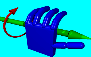
The left hand can also be used to determine rotation directions. To do this we must perform the famous Computer Graphics Aerobics exercise. We hold up our left hand and point our thumb in the positive direction of the axis of rotation. Our fingers will curl in the positive direction of rotation. Similarly if we point our thumb in the negative direction of the axis our fingers will curl in the negative direction of rotation.
In the above illustration, the left hand is curling around the x-axis. The thumb points in the positive x direction and the fingers curl over in the positive rotation direction.
If we want to use a right-handed system, as some CAD systems and modellers do, the right vector in the camera specification needs to be changed. See the detailed description in "Handedness". In a right-handed system we use our right hand for the Aerobics.
There is some controversy over whether POV-Ray's method of doing a right-handed system is really proper. To avoid problems we stick with the left-handed system which is not in dispute.
The first include statement reads in definitions for various useful colors. The second include statement reads in some useful shapes. The next read pre-defined finishes, glass, metal, stone and wood textures. It is a good idea to have a look through them to see but a few of the many possible shapes and textures available.
We should only include files we really need in our scene. Some of the include files coming with POV-Ray are quite large and we should better save the parsing time and memory if we don't need them. In the following examples we will only use the colors.inc, finish.inc and stones.inc include files so we will better remove the appropriate lines from our scene file.
We may have as many include files as needed in a scene file. Include files may themselves contain include files, but we are limited to declaring includes nested only ten levels deep.
Filenames specified in the include statements will be searched for in the current directory first and, if not found, will then be searched for in directories specified by any +L or Library_Path options active. This would facilitate keeping all our "include" (.inc) files such as shapes.inc, colors.inc and textures.inc in an "include" subdirectory, and giving an +L switch on the command line to where our library of include files are.
We add the following camera statement to the scene.
Briefly, location <0,2,-3> places the camera up two units and back three units from the center of the ray-tracing universe which is at <0,0,0>. By default +z is into the screen and -z is back out of the screen.
Also look_at <0,1,2> rotates the camera to point at the coordinates <0,1,2>. A point 5 units in front of and 1 unit lower than the camera. The look_at point should be the center of attention of our image.
The first vector specifies the center of the sphere. In this example the x coordinate is zero so it is centered left and right. It is also at y=1 or one unit up from the origin. The z coordinate is 2 which is five units in front of the camera, which is at z=-3. After the center vector is a comma followed by the radius which in this case is two units. Since the radius is half the width of a sphere, the sphere is four units wide.
The color we define is the way we want an object to look if fully illuminated. If we were painting a picture of a sphere we would use dark shades of a color to indicate the shadowed side and bright shades on the illuminated side. However ray-tracing takes care of that. We pick the basic color inherent in the object and POV-Ray brightens or darkens it depending on the lighting in the scene. Because we are defining the basic color the object actually has rather than how it looks the parameter is called pigment.
Many types of color patterns are available for use in a pigment statement. The keyword color specifies that the whole object is to be one solid color rather than some pattern of colors. We can use one of the color identifiers previously defined in the standard include file colors.inc.
If no standard color is available for our needs, we may define our own color by using the color keyword followed by red, green and blue keywords specifying the amount of red, green and blue to be mixed. For example a nice shade of pink can be specified by:
The values after each keyword should be in the range from 0.0 to 1.0. Any of the three components not specified will default to 0. A shortcut notation may also be used. The following produces the same shade of pink:
Colors are explained in more detail in section "Specifying Colors".
to the scene file to get our first complete POV-Ray scene file as shown below.
The vector in the light_source statement specifies the location of the light as two units to our right, four units above the origin and three units back from the origin. The light source is invisible, it only casts light, so no texture is needed.
That's it! We close the file and render a small picture of it using the command
If our computer does not use the command line, we have to read the platform specific docs for the correct command to render the scene.
We may also set any other command line options we like. The scene is written to the image file demo.tga (or some suffix other than .tga if our computer uses a different default file format).
The scene we just traced isn't quite state of the art but we will have to start with the basics before we soon get to much more fascinating features and scenes.
We create a new file called focaldem.pov and enter the following text
Now we can proceed to place our focal blur camera to an appropriate viewing position. Straight back from our three objects will yield a nice view. Adjusting the focal point will move the point of focus anywhere in the scene. We just add the following lines to the file:
The focal point is simply the point at which the focus of the camera is at its sharpest. We position this point in our scene and assign a value to the aperture to adjust how close or how far away we want the focal blur to occur from the focused area.
The aperture setting can be considered an area of focus. Opening up the aperture has the effect of making the area of focus smaller while giving the aperture a smaller value makes the area of focus larger. This is how we control where focal blur begins to occur around the focal point.
The blur samples setting determines how many rays are used to sample each pixel. Basically, the more rays that are used the higher the quality of the resultant image, but consequently the longer it takes to render. Each scene is different so we have to experiment. This tutorial has examples of 4 and 20 samples but we can use more for high resolution images. We should not use more samples than is necessary to achieve the desired quality - more samples take more time to render. The confidence and variance settings are covered in section "Focal Blur".
We experiment with the focal point, aperture, and blur sample settings. The scene has lines with other values that we can try by commenting out the default line with double slash marks and un-commenting the line we wish to try out. We make only one change at a time to see the effect on the scene.
Two final points when tracing a scene using a focal blur camera. We needn't specify anti-aliasing (the \Clo{+A} switch) because the focal blur code uses its one sampling method that automatically takes care of anti-aliasing. Focal blur can only be used with the perspective camera.+D?3 Use 332 palette with dithering (default and best for VGA systems). This is a fixed palette of 256 colors with each color consisting 3-bits of red data, 3-bits green and 2-bits blue. +D?0 Use HSV palette option for VGA display. This is a fixed palette of 256 colors where colors are matched according to hue, saturation and intensity rather than the amount of red, green and blue. +D?G Use fixed gray scale palette option for VGA display. +D?H Use HiColor option. Displays more than 32,000 colors with dithering. Supported on VESA, SpeedSTAR 24X, ATI XL HiColor and Tseng 4000 based cards with high color 15 or 16 bit options. +D?T For Truecolor 24 bit cards. Use 24 bit color. Supported on the Diamond SpeedSTAR 24X and cards with 24-bit VESA support only.
   +D0H Auto detect the VGA display type and display the image to the
        screen as it's being worked on. Use the 15-bit HiColor chip and
        dithering to display more than 32,000 colors on screen.
   +D4  Display to a TSENG 4000 chipset VGA using the 332 palette option.
   +D4H Display to a TSENG 4000 chipset VGA using the HiColor option.
   +DG0 Display to a VESA VGA adapter and use the HSV palette option.
   +DG3 Display to a VESA VGA adapter and use the 332 palette option.
   +DGH Display to a VESA VGA adapter and use the HiColor option for
        over 32,000 colors.
   +DGT Display to a VESA VGA adapter and use the TrueColor option for
        over 16 million colors.
Section 4
Beginning Tutorial
Section 4.1
Our First Image
Section 4.1.1
Understanding POV-Ray's Coordinate System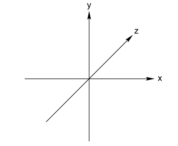
The left-handed coordinate system (the z-axis is pointing away).
"Computer Graphics Aerobics" to determine the rotation direction.
Section 4.1.2
Adding Standard Include Files
Section 4.1.3
Adding a Camera
Section 4.1.4
Describing an Object
Section 4.1.5
Adding Texture to an Object
Section 4.1.6
Defining a Light Source
povray +w160 +h120 +p +x +d0 -v -idemo.pov
Section 4.2
Using the Camera
Section 4.2.1
Using Focal Blur
Table Of Contents