Section 4.8.5
Halos
Halos are a powerful feature that can be used to create a lot of different effects like clouds, fogs, fire, lasers, etc. The name actually comes from the ability to render halos with it, like the ones seen around the moon or the sun.
Due to the complexity of the halo feature and the large amount of parameters provided it is very difficult to get satisfying results. The following sections will help to create a halo step by step, starting with the basic things and going to the more subtle stuff.
It is also helpful to read the halo reference sections to get a better understanding of the halo feature. One should especially read the sections "Empty and Solid Objects" and "Halo Mapping" because they are essential for understanding halos.
A halo is attached to an object, the so called container object, just like a pigment, normal or finish. The container object is completely filled by the halo but we will not see anything if we do not make sure that the object is hollow and the surface is translucent. How this is accomplished will be shown in the next section.
When working with halos we always have to keep in mind that the container object has to be hollow and translucent.
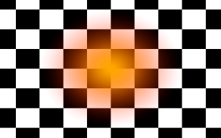
In the first example (halo01.pov) we try to create a fiery explosion, which the sphere is best suited for. We start with a simple scene consisting of a camera, a light source (we don't care about shadows so we add the shadowless keyword), a checkered plane and a unit-sized sphere containing the halo.
We note that the sphere is set to be hollow and has a translucent surface (the transmittance channel in the pigment's color is 1), just like it is required for halos. We also note that the plane has a hollow keyword even though it has no halo. Why is this necessary?
The reason is quite simple. As described in section "Empty and Solid Objects" there can be no halo inside any other non-hollow object. Since the camera is inside the plane object, i. e. it is on the side of the plane that is considered to be inside, the halo will never be visible unless the plane is made hollow (or the negative keyword is added to bring the camera on the outside side of the plane).
What do all those halo keywords and values mean? At the beginning of the halo the emitting keyword is used to specify what type of halo we want to use. The emitting halo emits light. That is what is best suited for our fiery explosion.
The spherical_mapping and linear keywords need a more detailed explanation of how a halo works (this is also done in chapter "Halo" in more detail).
As noted above the halo is made up of lots of small particles. The distribution of these particles is described by a density function. In general, a density function tells us how much particles we'll find at a given location.
Instead of using an explicitly, mathematical density function, halos rely on a given set of density mappings and density functions to model a variety of particle distributions.
The first step in this model is the density mapping function that is used to map three-dimensional points onto a one-dimensional range of values. In our example we use a spherical mapping, i.e. we take the distance of a point from the center of the coordinate system. This is the reason why it is clever to start with a container object sitting on the coordinate system's center. Since all density mappings are made relative to this center we won't see anything if we start with an object sitting somewhere else. Moving the whole object (including textures and halos) to another location is the correct way of placing a container object.
Now we have a single value in the range from 0 to 1. This value will be transformed using a density function to get density values instead of distance values. Just using this single value won't work because we want to have particle distributions were the density decreases as we move from the center of the container object to the outside.
This is done by the density function. There are several alternatives available as described in the halo reference (see section "Density Function"). We use the simple linear function that just maps values between 0 and 1 onto a 1 to 0 range. Thus we get a density value of 1 at the center of our sphere and a value of 0 at its surface.
Now that we have a density function what do we do to see something? This is where the colour_map keyword comes into play. It is used to describe a color map that actually tells the program what colors are to be used for what density. The relation is quite simple: colors at the beginning of the color map (with small values) will be used for low density values and colors at the end of the map (high values) will be used for high densities. In our example the halo will be yellow at the center of the sphere where the density is greatest and it will blend to red at the surface of the sphere where the density approaches zero.
The transmittance channel of the colors in the color map is used to model the translucency of the density field. A value of 0 represents no translucency, i. e. that areas with the corresponding density will be (almost) opaque, while a value of 1 means (almost) total translucency.
In our example we use
which results in a halo with a very translucent, reddish outer area and a nearly opaque, yellowish inner areas as we can see after tracing the example image.
There is one parameter that still needs to be explained: the samples keyword. This keyword tells POV-Ray how many samples have to be taken along any ray traveling through the halo to calculate its effect. Using a low value will result in a high tracing speed while a high value will lead to a low speed. The sample value has to be increased if the halo looks somewhat noisy, i. e. if some artifacts of the low sampling rate appear. For more details see section "Halo Sampling".
A good starting value for the number of samples is 10.
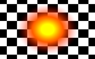
Looking at the result of halo02.pov we see that the halo is indeed much brighter.
This is done by using the turbulence keyword together with the amount of turbulence we want to add. Just like in the following example.
Adding turbulence to the halo moves all points inside the halo container in a pseudo-random manner. This results in a particle distribution that looks like there was some kind of flow in the halo (depending on the amount of turbulence we'll get a laminar or turbulent flow). The high turbulence value is used because an explosion is highly turbulent.
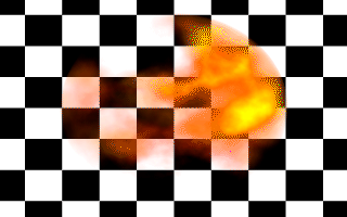
Looking at the example image (halo03.pov) we'll see that this looks more like a fiery explosion than the glowing ball we got until now.
We notice that the time it took to render the image increased after we added the turbulence. This is due to the fact that for every sample taken from the halo the slow turbulence function has to be evaluated.
As noted above adding turbulence moves the particles inside the halo container around. The problem is that some of the particles are actually moved out of the container object. This leads to high densities at the surface of the container object revealing the shape of the object (all particles outside the container are lost and will not visible resulting in a large, highly visible density change at the surface).
An easy way of avoiding this is to make sure that the particles stay inside the container object even if we add some turbulence. This is done by scaling the halo to reduce its size. We do not scale the container object, just the halo.
This is done by adding the scale keyword inside the halo statement.
The scale 0.5 command tells POV-Ray to scale all points inside the halo by this amount. This effectively scales the radius we get after the density mapping to a range of 0 to 0.5 instead of 0 to 1 (without turbulence). If we now add the turbulence the points are allowed to move half a unit in every direction without leaving the container object. That is exactly what we want.
To compensate for the smaller halo we would get we scale the sphere (and the halo inside) by 1.5.
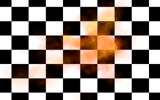
Looking at the new example image (halo04.pov) we will no longer see any signs of the container sphere. We finally have a nice fiery explosion.
The amount by which to scale the halo depends on the amount of turbulence we use. The higher the turbulence value the smaller the halo has to be scaled. That is something to experiment with.
Another way to avoid that points move out of the sphere is to use a larger sphere, i. e. a sphere with a radius larger than one. It is important to re-size the sphere before the halo is added because otherwise the halo will also be scaled.
We note that this only works for spherical and box mapping (and a non-constant density function). All other mapping types are (partially) infinite, i. e. the resulting particle distribution covers an infinite space (see also "Halo Mapping").
Section 4.8.5.1
What are Halos?
Section 4.8.5.2
The Emitting Halo
Section 4.8.5.2.1
Starting with a Basic Halo
The basic halo used in modelling a fiery explosion.
Section 4.8.5.2.2
Increasing the Brightness
The halo is much brighter now.
Section 4.8.5.2.3
Adding Some Turbulence
Adding some turbulence makes the fiery explosion more realistic.
Section 4.8.5.2.4
Resizing the Halo
Resizing the halo makes it look much better.
Table Of Contents