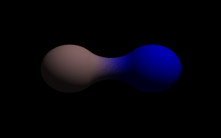
A simple, two-part blob.
A slightly more mathematical way of describing a blob would be to say that it is one object made up of two or more component pieces. Each piece is really an invisible field of force which starts out at a particular strength and falls off smoothly to zero at a given radius. Where ever these components overlap in space, their field strength gets added together (and yes, we can have negative strength which gets subtracted out of the total as well). We could have just one component in a blob, but except for seeing what it looks like there is little point, since the real beauty of blobs is the way the components interact with one another.
Let us take a simple example blob to start. Now, in fact there are a couple different types of components but we will look at them a little later. For the sake of a simple first example, let us just talk about spherical components. Here is a sample POV-Ray code showing a basic camera, light, and a simple two component blob (this scene is called blobdem1.pov):
The threshold is simply the overall strength value at which the blob becomes visible. Any points within the blob where the strength matches the threshold exactly form the surface of the blob shape. Those less than the threshold are outside and those greater than are inside the blob.
We note that the spherical component looks a lot like a simple sphere object. We have the sphere keyword, the vector representing the location of the center of the sphere and the float representing the radius of the sphere. But what is that last float value? That is the individual strength of that component. In a spherical component, that is how strong the component's field is at the center of the sphere. It will fall off in a linear progression until it reaches exactly zero at the radius of the sphere.
Before we render this test image, we note that we have given each component a different pigment. POV-Ray allows blob components to be given separate textures. We have done this here to make it clearer which parts of the blob are which. We can also texture the whole blob as one, like the finish statement at the end, which applies to all components since it appears at the end, outside of all the components. We render the scene and get a basic kissing spheres type blob.
The image we see shows the spheres on either side, but they are smoothly joined by that bridge section in the center. This bridge represents where the two fields overlap, and therefore stay above the threshold for longer than elsewhere in the blob. If that is not totally clear, we add the following two objects to our scene and re-render (see file blobdem2.pov). We note that these are meant to be entered as separate sphere objects, not more components in the blob.
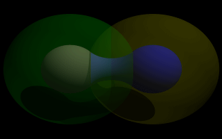
Now the secrets of the kissing spheres are laid bare. These semi-transparent spheres show where the components of the blob actually are. If we have not worked with blobs before, we might be surprised to see that the spheres we just added extend way farther out than the spheres that actually show up on the blobs. That of course is because our spheres have been assigned a starting strength of one, which gradually fades to zero as we move away from the sphere's center. When the strength drops below the threshold (in this case 0.65) the rest of the sphere becomes part of the outside of the blob and therefore is not visible.
See the part where the two transparent spheres overlap? We note that it exactly corresponds to the bridge between the two spheres. That is the region where the two components are both contributing to the overall strength of the blob at that point. That is why the bridge appears: that region has a high enough strength to stay over the threshold, due to the fact that the combined strength of two spherical components is overlapping there.
Before we move on to cylinders, it should perhaps be mentioned that the old style of components used in previous versions of POV-Ray still work. Back then, all components were spheres, so it was not necessary to say sphere or cylinder. An old style component had the form:
This has the same effect as a spherical component, just as we already saw above. This is only useful for backwards compatibility. If we already have POV-Ray files with blobs from earlier versions, this is when we would need to recognize these components. We note that the old style components did not put braces around the strength, radius and center, and of course, we cannot independantly transform or texture them, so if we are modifying an older work into a new version, it may arguably be of benefit to convert old style components into spherical components anyway.
Now for something new and different: cylindrical components. It could be argued that all we ever needed to do to make a roughly cylindrical portion of a blob was string a line of spherical components together along a straight line. Which is fine, if we like having extra to type, and also assuming that the cylinder was oriented along an axis. If not, we would have to work out the mathematical position of each component to keep it is a straight line. But no more! Cylindrical components have arrived.
We replace the blob in our last example with the following and re-render. We can get rid of the transparent spheres too, by the way.
We only have one component so that we can see the basic shape of the cylindrical component. It is not quite a true cylinder - more of a sausage shape, being a cylinder capped by two hemi-spheres. We think of it as if it were an array of spherical components all closely strung along a straight line.
As for the component declaration itself: simple, logical, exactly as we would expect it to look (assuming we have been awake so far): it looks pretty much like the declaration of a cylinder object, with vectors specifying the two endpoints and a float giving the radius of the cylinder. The last float, of course, is the strength of the component. Just as with spherical components, the strength will determine the nature and degree of this component's interaction with its fellow components. In fact, next let us give this fellow something to interact with, shall we?
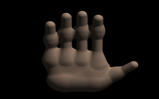
As we can guess from the comments, we are building a hand here. After we render this image, we can see there are a few problems with it. The palm and heel of the hand would look more realistic if we used a couple dozen smaller components rather than the half dozen larger ones we have used, and each finger should have three segments instead of two, but for the sake of a simplified demonstration, we can overlook these points. But there is one thing we really need to address here: This poor fellow appears to have horrible painful swelling of the joints!
A review of what we know of blobs will quickly reveal what went wrong. The joints are places where the blob components overlap, therefore the combined strength of both components at that point causes the surface to extend further out, since it stays over the threshold longer. To fix this, what we need are components corresponding to the overlap region which have a negative strength to counteract part of the combined field strength. We add the following components to our blob (see file blobdem4.pov).
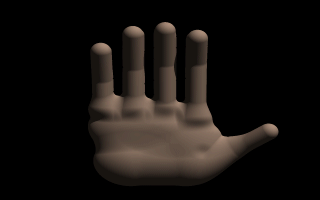
Much better! The negative strength of the spherical components counteracts approximately half of the field strength at the points where to components overlap, so the ugly, unrealistic (and painful looking) bulging is cut out making our hand considerably improved. While we could probably make a yet more realistic hand with a couple dozen additional components, what we get this time is a considerable improvement. Any by now, we have enough basic knowledge of blob mechanics to make a wide array of smooth, flowing organic shapes!
We make a new file called image.pov and edit it to contain the following:
The hf_gray_16 keyword causes the output to be in a special 16 bit grayscale that is perfect for generating height fields. The normal 8 bit output will lead to less smooth surfaces.
Now we create a camera positioned so that it points directly down the z-axis at the origin.
We then create a plane positioned like a wall at z=0. This plane will completely fill the screen. It will be colored with white and gray wrinkles.
Finally, create a light source.
We render this scene at 640x480 +A0.1 +FT. We will get an image that will produce an excellent height field. We create a new file called hfdemo.pov and edit it as follows:
We add a camera that is two units above the origin and ten units back ...
... and a light source.
Now we add the height field. In the following syntax, a Targa image file is specified, the height field is smoothed, it is given a simple white pigment, it is translated to center it around the origin and it is scaled so that it resembles mountains and fills the screen.
We save the file and render it at 320x240 -A. Later, when we are satisfied that the height field is the way we want it, we render it at a higher resolution with anti-aliasing.
Wow! The Himalayas have come to our computer screen!
Here is some source for a really basic lathe (called lathdem1.pov).
We render this, and what we see is a fairly simply type of lathe, which looks like a child's top. Let's take a look at how this code produced the effect.
First, a set of six points are declared which the raytracer connects with lines. We note that there are only two components in the vectors which describe these points. The lines that are drawn are assumed to be in the x-y-plane, therefore it is as if all the z-components were assumed to be zero. The use of a two-dimensional vector is mandatory (Attempting to use a 3D vector would trigger an error... with one exception, which we will explore later in the discussion of splines).
Once the lines are determined, the ray-tracer rotates this line around the y-axis, and we can imagine a trail being left through space as it goes, with the surface of that trail being the surface of our object.
The specified points are connected with straight lines because we used the linear_spline keyword. There are other types of splines available with the lathe, which will result in smooth curving lines, and even rounded curving points of transition, but we will get back to that in a moment.
First, we would like to digress a moment to talk about the difference between a lathe and a surface of revolution object (SOR). The SOR object, described in a separate tutorial, may seem terribly similar to the lathe at first glance. It too declares a series of points and connects them with curving lines and then rotates them around the y-axis. The lathe has certain advantages, such as different kinds of splines, linear, quadratic and cubic, and one more thing:
The simpler mathematics used by a SOR doesn't allow the curve to double back over the same y-coordinates, thus, if using a SOR, any sudden twist which cuts back down over the same heights that the curve previously covered will trigger an error. For example, suppose we wanted a lathe to arc up from <0,0> to <2,2>, then to dip back down to <4,0>. Rotated around the y-axis, this would produce something like a gelatin mold - a rounded semi torus, hollow in the middle. But with the SOR, as soon as the curve doubled back on itself in the y-direction, it would become an illegal declaration.
Still, the SOR has one powerful strong point: because it uses simpler order mathematics, it generally tends to render faster than an equivalent lathe. So in the end, its a matter of: we use a SOR if its limitations will allow, but when we need a more flexible shape, we go with the lathe instead.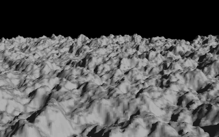
A height field created completely with POV-Ray.
Section 4.4.4
Lathe Object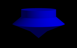
A simple lathe object.
Table Of Contents