Section 4.10.4
The Atmosphere
The atmosphere feature can be used to model the interaction of light with particles in the air. Beams of light will become visible and objects will cast shadows into the fog or dust that's filling the air.
The atmosphere model used in POV-Ray assumes a constant particle density everywhere except solid objects. If you want to create cloud like fogs or smoke you'll have to use the halo texturing feature described in section "Halos".
Imagine a simple room with a window. Light falls through the window and is scattered by the dust particles in the air. You'll see beams of light coming from the window and shining on the floor.
We want to model this scene step by step. The following examples start with the room, the window and a spotlight somewhere outside the room. Currently there's no atmosphere to be able to verify if the lighting is correct (atmos1.pov).
The point light source is used to illuminate the room from inside without any interaction with the atmosphere. This is done by adding atmosphere off . We don't have to care about this light when we add the atmosphere later.
The spotlight is used with the atmospheric_attenuation keyword. This means that light coming from the spotlight will be diminished by the atmosphere.
The union object is used to model the room and the window. Since we use the difference between two boxes to model the room (the first two boxes in the difference statement) there is no need for setting the union hollow. If we are inside this room we actually will be outside the object (see also "Using Hollow Objects and Atmosphere").
The type keyword selects the type of atmospheric scattering we want to use. In this case we use the isotropic scattering that equally scatters light in all directions (see "Atmosphere" for more details about the different scattering types).
The samples keyword determines the number of samples used in accumulating the atmospheric effect. For every ray samples are taken along the ray to determine whether a sample is lit by a light source or not. If the sample is lit the amount of light scattered into the direction of the viewer is determined and added to the total intensity.
You can always start with an arbitrary number of samples. If the results do not fit your ideas you can increase the sampling rate to get better results. The problem of choosing a good sampling rate is the trade-off between a satisfying image and a fast rendering. A high sampling rate will almost always work but the rendering will also take a very long time. That's something to experiment with.
The distance keyword specifies the density of the atmosphere. It works in the same way as the distance parameter of the fog feature.
Last but not least will the scattering value determine the amount of light that is scattered by the particles (the remaining light is absorbed). As you'll later see this parameter is very useful in adjusting the overall brightness of the atmosphere.
Looking at the image created from the above scene you'll notice some very ugly anti-aliasing artifacts known as mach-bands. They are the result of a low sampling rate.
How this effect can be avoid is described in the following section.
The brute force approach is to increase the sampling rate until the artifacts vanish and you get a satisfying image. Though this will always work it is a bad idea because it is very time consuming. A better approach is to use jittering and anti-aliasing first. If both features don't help you'll have to increase the sampling rate.
Jittering moves each sample point by a small, random amount along the sampling direction. This helps to reduce regular features resulting from aliasing. There is (hardly) nothing more annoying to the human visual system than the regular features resulting from a low sampling rate. It's much better to add some extra noise to the image by jittering the sample positions. The human eye is much more forgiving to that.
Use the jitter keyword followed by the amount of jittering you want to use. Good jittering values are up to 0.5, higher values result in too much noise.
You should be aware that jittering can not fix the artifacts introduced by a too low sampling rate. It can only make them less visible.
An additional and better way of reducing aliasing artifacts is to use (adaptive) super-sampling. This method casts additional samples where it is likely that they are needed. If the intensity between two adjacent samples differs too much additional samples are taken in-between. This step is done recursively until a specified recursion level is reached or the sample get close to each other.
The aa_level and aa_threshold keywords give full control over the super-sampling process. The aa_level keyword determines the maximum recursion level while aa_threshold specifies the maximum allowed difference between two sample before the super-sampling is done.
After all this theory we get back to our sample scene and add the appropriate keywords to use both jittering and super-sampling (atmos3.pov).
A very low threshold value was chosen to super-sample even between adjacent points with a very similar intensity. The maximum recursion level of 4 will lead to a maximum of fifteen super-samples.
If you are looking at the results that you get after adding jittering and super-sampling you won't be satisfied. The only way of reducing the still visible artifacts is to increase the sampling rate by choosing a higher number of samples.
Doing this you'll get a good result showing (almost) no artifacts. BTW, the amount of dust floating around in this room may be a little bit exaggerated but it's just an example. And examples tend to be exaggerated.
If you want to create a reddish atmosphere for example, you can add the following line to the atmosphere statement used in the above example.
Just using rgb <1,0,0> does not work because the color's filter value will be zero and thus no light will be filtered by the color, i. e. no light will be multiplied with the color's RGB components.
The filter value of 0.25 means that 25% of the light passing through the atmosphere will be filtered by the red color and 75% will pass unfiltered.
The transmittance channel of the atmosphere's color is used to specify a minimum translucency. By default the transmittance channel is zero and thus there is no such minimum translucency. Using a positive value lets you determine the amount of background light that will always pass through the atmosphere, regardless of its thickness set by the distance keyword.
If you use e.g. a color of rgbt <0,0,0,0.3> with our room example you can make the blue background become visible. Until now it was hidden by the atmosphere.
The best approach is to choose the distance value first. This value determines the visibility of the objects in the scene regardless of atmospheric light scattering. It works in the same way as the distance value of the fog feature.
Since fog is very similar to the unlit atmosphere you can use a fog instead of an atmosphere to quickly choose a working distance value. If you do this with room scene we used earlier you would use the following fog statement instead of the atmosphere (atmos4.pov).
The black color is used to simulate the attenuation you'll get in those parts of the atmosphere scene lying in shadow.
If you want to use a colored atmosphere you'll have to use the same color for the fog as you want to use for the atmosphere, including the filter and transmittance channel values (see "Using a Coloured Atmosphere" and "Atmosphere" for an explanation of the atmosphere's color).
If you (roughly) want to simulate the appearance of those parts lit by a light source you can use the color of the atmosphere inside the fog statement instead.
After you are satisfied with the distance value you'll have to choose a scattering value. This value lets you fit the atmosphere's intensity to your needs. Starting with a value of one you have to increase the value if the atmosphere effects are hardly visible. If you don't see anything in the lit parts of the atmosphere you'll have to decrease the value.
You should be aware that you may have to use very small or very large values to get the desired results.
If you want to add a light source that does not interact with the atmosphere you can use the atmosphere keyword inside the light source statement (see "Atmosphere Interaction"). Just add atmosphere off.
By default the light coming from any light source will not be diminished by the atmosphere. Thus the highlights in your scene will normally be too bright. This can be changed with atmospheric_attenuation on.
The Rayleigh scattering is used for small particles like dust and smoke while the Mie scattering is used for fog.
If you ever saw the lighthouse scene in the movie Casper you'll know what effect the scattering type has. In this scene the beam of light coming from the lighthouse becomes visible while it points nearly towards the viewer. As it starts to point away from the viewer it vanishes. This behaviour is typical for minuscule water droplets as modeled by the Mie scattering.
Even though this is not obvious this holds for infinite and patch objects like quadrics, quartics, triangles, polygons, etc. Whenever you add one of those objects you should add the hollow keyword as long as you are not absolutely sure you don't need it. You also have to make sure that all objects the camera is inside are set to be hollow.
Whenever you get unexpected results you should check for solid objects and set them to be hollow.
The size and shape of the rainbow are determined by the angle and width keywords. The direction keyword is used to set the direction of the incoming light, thus setting the rainbow's position. The rainbow is visible when the angle between the direction vector and the incident light direction is larger than angle-width/2 and smaller than angle+width/2.
The incoming light is the virtual light source that is responsible for the rainbow. There needn't be a real light source to create the rainbow effect.
The rainbow is a fog-like effect, i.e. the rainbow's color is mixed with the background color based on the distance to the intersection point. If you choose small distance values the rainbow will be visible on objects, not just in the background. You can avoid this by using a very large distance value.
The color map is the crucial part of the rainbow since it contains all the colors that normally can be seen in a rainbow. The color of the innermost color band is taken from the color map entry 0 while the outermost band is take from entry 1. You should note that due to the limited color range any monitor can display it is impossible to create a real rainbow. There are just some colors that you cannot display.
The filter channel of the rainbow's color map is used in the same way as with fogs. It determines how much of the light passing through the rainbow is filtered by the color.
The following example shows a simple scene with a ground plane, three spheres and a somewhat exaggerated rainbow (rainbow1.pov).
Some irregularity is added to the color bands using the jitter keyword.
The rainbow in our sample is much too bright. You'll never see a rainbow like this in reality. You can decrease the rainbow's colors by decreasing the RGB values in the color map.
Section 4.10.4.1
Starting With an Empty Room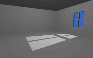
The empty room we want to start with.
Section 4.10.4.2
Adding Dust to the Room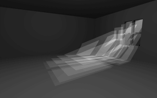
After adding some dust beams of light become visible.
Section 4.10.4.3
Choosing a Good Sampling Rate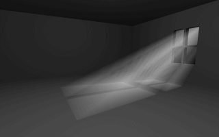
A high sampling rate leads to a satisfying image.
Section 4.10.4.4
Using a Coloured Atmosphere
Section 4.10.4.5
Atmosphere Tips
Section 4.10.4.5.1
Choosing the Distance and Scattering Parameters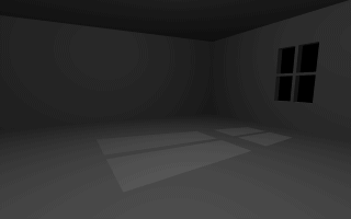
A black fog can be used to get a working distance value for the atmosphere.
Section 4.10.4.5.2
Atmosphere and Light Sources
Section 4.10.4.5.3
Atmosphere Scattering Types
Section 4.10.4.5.4
Increasing the Image Resolution
Section 4.10.4.5.5
Using Hollow Objects and Atmosphere
Section 4.10.5
The Rainbow
Section 4.10.5.1
Starting With a Simple Rainbow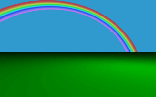
A colorful rainbow.
Table Of Contents